6.13. Quantum Fourier Transform (QFT)
The Quantum Fourier Transform (QFT) plays a central role in quantum computing and is a critical component in significant quantum algorithms such as Shor’s Algorithm. This section will focus on QFT in detail.
6.13.1 What is the Quantum Fourier Transform?
The Quantum Fourier Transform is the quantum version of the classical Fourier transform. While the classical Fourier transform decomposes a function into its frequency components, QFT transforms quantum states into their frequency components in a similar manner. By leveraging linear algebra and signal processing capabilities in quantum computing, QFT accelerates the solution of specific problems.
Mathematically, QFT transforms a quantum state as follows:
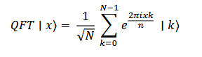
Where:
- |x⟩ and |k⟩ are the basis states of the quantum bits (qubits).
- N = 2n, representing the total number of states in a system with n qubits.
- 𝑒2πi𝑥𝑘 / 𝑁 is the complex phase factor.
6.13.2. Fourier Transform
In the classical Fourier transform, a function’s time (or spatial) components are decomposed into frequency components. QFT is the quantum version of this transform and performs the same operation using quantum superpositions.
6.13.2.1. Mathematical Definition of QFT
For a quantum state ∣x⟩ with n qubits, QFT transforms the state as follows:
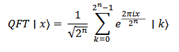
This transformation is the quantum version of the classical Fourier transform, based on the same principles but utilizing quantum superposition and parallel processing capabilities.
6.13.3. Implementation of QFT in Quantum Circuits
The implementation of QFT in quantum circuits involves a combination of specific quantum gates. QFT is performed through the following essential steps:
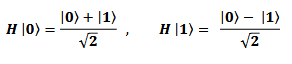
6.13.3.1. Hadamard Gate
The Hadamard gate places a qubit into a superposition state. Starting with a qubit state of ∣0⟩ or ∣1⟩, it operates as follows:
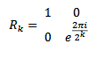
6.13.3.2. Controlled Phase Gates
Controlled phase gates establish phase relationships between two qubits. One of the most commonly used gates is the Rk gate, which is defined as:
6.13.3.3. QFT Circuit
For an n-qubit QFT circuit, the following steps are performed:
- Applying the Hadamard Gate: The Hadamard gate is applied to the first qubit.
- Controlled Phase Gates: Controlled Rk gates are applied to all subsequent qubits after the first qubit.
- Reordering the Qubits: Due to the symmetric nature of QFT, the qubits are rearranged in reverse order using swap operations.
- Repeating the Process: The same steps are repeated for each subsequent qubit, applying the Hadamard gate and controlled phase gates as needed.
6.13.3.4. Example of a QFT Circuit
A simple 2-qubit QFT circuit includes the following steps:
- Hadamard Gate: Apply a Hadamard gate to qubit 0.
- Controlled R2 Gate: Use qubit 1 as the control qubit to apply an R2 gate to qubit 0.
- Swap Gates: Swap the positions of qubit 0 and qubit 1.
As a result, the input state ∣x⟩ is transformed into a new quantum state where the QFT has been applied.